|
Here's the most simple (and very old and well known) power-up delay circuit I used for my DIY tube amp and class A solid state (IC) amp. It is very primitive but it may be useful to you if you're more n00b than me ;-) In the tube amp it delays anode power supply up for 20-30 seconds while the tubes are heating to their working temperature to reduce "wearing" of the tubes. In the class A IC amp there are 2 relay switches (connected in parallel) which keep the speakers disconnected from the amp for about 5 seconds after turning it on to keep them away from class A bias DC while the IC's are powering up and stabilizing. 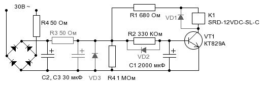 The supply voltage can be anything what you have at hand in your amp, but at least about 1.5-2 times higher than relay's voltage to accommodate voltage drop on the transistor. All diodes, capacitors and the transistor must have their voltage rating at least 1.3 of rectified supply voltage. R2, R4 may have almost any power rating, say, 0.25 Wt or more. The other resistors should be 1-2 Wt. R3 value must be picked so VT1 is fully open when the cap in its base is fully charged (or without the cap disconnected), but not too small. R1 must be picked so when the transistor is open voltage drop around the relay (K1) is in relay's working range. Then the cap in transistor's base (C1) is found for the desired delay time. It depends on supply voltage, values of all components, certain relay and transistor species you used so you have to try. C2, C3 are power supply filters and their values don't matter much, just make sure they're big enough so the relay turns on confidently and doesn't ring after that. Please note that delay time may vary by some degree with supply voltage fluctuations, residual charge in C1, "mood" of the relay and may decrease with C1 ageing (and lose of some of its capacity). This is the main drawback of the scheme. So it's good idea to tune delay to be about 2 times longer than you actually need to be on the safe side. Archives
|
Blogs :Categories :Search :MiscPowered by |
 |
| BLOG OPEN SOURCE PHOTOGRAPHY ARCHIVE CONTACTS |