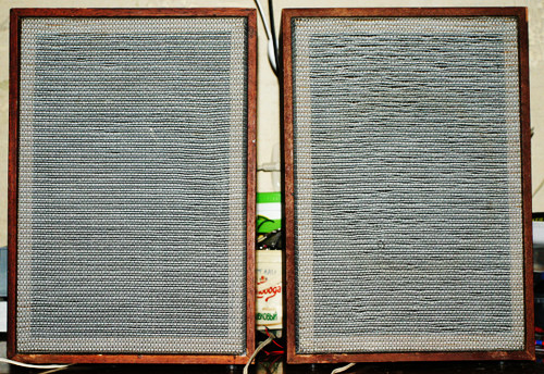
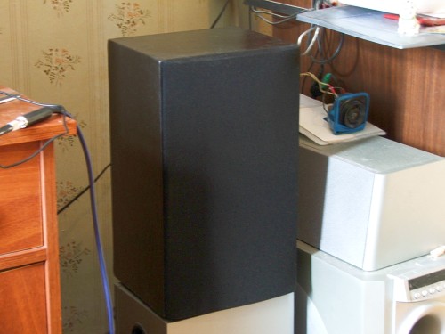
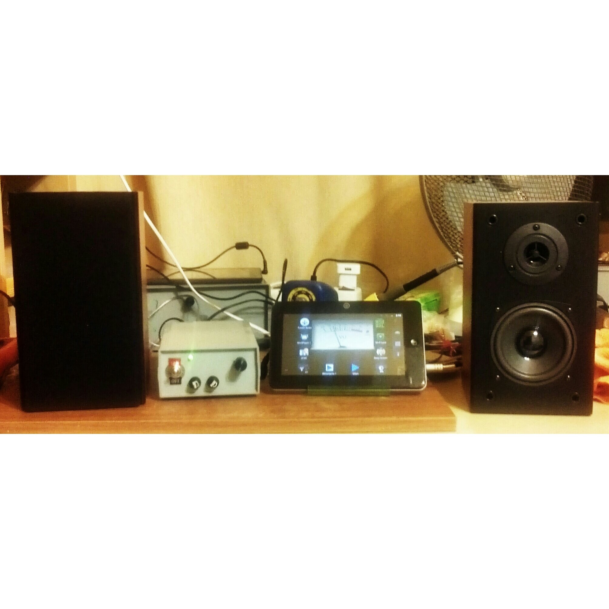
Category: СамодельщикМоддинг (aka переделка, доработка, апгрейд) колонок Свен SPS-611Небольшой моддинг свеновских двухполосных стереоколонок, которые мне случайно достались, как неисправные. Мои колонки довольно старые, в районе 8-10 лет, но, похоже, они мало отличаются от нынешнего производства, только усилок внутри перенесли, чтобы ручки стали сбоку, а не сзади. Вскрытие показало, что причина поломки - отвалившийся провод, однако, я решил не тратить время на родные потроха и сразу их выкинул. Там был совершенно типичный встроенный усилитель на ИМС с тембрами "НЧ" и "ВЧ". 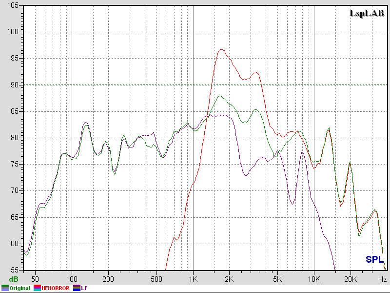 Понятно, что с такими колонками единственное разумное положение темброблока - когда НЧ и ВЧ выкручены до упора. Итак, Hi-Fi из этого сделать нельзя, но хотелось бы, чтобы по крайней мере было ровно, не требовало "тембров" и просто не выносило слух. Что получилось с фильтром: Токовый усилитель для 4ГД-35Наконец-то выкладываю схему и замеры своей активной открытой системы на базе 8АС-4 (по 2 динамика 4ГД-35 в колонке, открытый ящик). Начинал делать в 2009 году, с тех пор она в разных стадиях готовности и эксплуатируется, в основном в спальне.  Ремонт задней крышки сотикаВнезапный способ ремонта задней крышки сотового телефона, которая была сломана 6 лет. Новую на замену уже не найти (модель телефона - 2003 года, Alcatel OT-525). Вклеил болтик  10ГДШ1-4, или +-2 дБ из мусоркиЭксперимент по выравниванию колонок от кассетного магнитофона "Маяк-223". Интересовал вопрос - а что будет, если взять копеечный динамик, и выровнять его АЧХ до уровня профессиональных мониторов? И тут на голову свалились эти колонки, причём в отличном состоянии (за исключением подвесов) - с гнилыми динамиками и ящиками я уже зарёкся связываться. Внешний вид АС - традиционный для 70-х годов. Плотные тряпочные грили достаточно на большом расстоянии от передней панели и непрозрачны, поэтому способны скрыть любой позор. Кстати, они были несъёмными (привинчены шурупами, которые от времени "приросли" и их пришлось высверлить): Колонки на базе S-30A: ReloadedНекоторое время назад эксгумировал с дальней полки и переделал свой первый, учебный проект апгрейда АС - S-30A (см. старые посты по тегу): Archives
|
Blogs :Categories :Search :MiscPowered by |
 |
| BLOG OPEN SOURCE PHOTOGRAPHY ARCHIVE CONTACTS |